The instruction register (IR) holds the instruction currently being executed. It’s loaded from memory during the Fetch stage of the execution cycle, and its contents are inspected by the control unit to decide what the processor does next.
When the PC hands an address to memory and Read is asserted, memory returns the encoded instruction word on the data bus. That word lands in IR. From there, the control unit decodes the opcode (which operation), source/destination register fields, and any immediate value embedded in the instruction.
What IR holds
For a fixed-length 32-bit RISC instruction, IR holds 32 bits divided into fields:
[ opcode | rd | rs | rt | imm/funct ]
The exact layout depends on the ISA. For Nios II:
R-type:  [ opcode | A | B | C | shift | funct ]   // register-register
I-type:  [ opcode | A | B |    immediate     ]    // register-immediate
J-type:  [ opcode |        target address     ]   // jump
The control unit pulls these fields out of IR with hard-wired bit-slice connections, no decoding required for the field positions themselves. The opcode tells it what type of instruction it is, and the rest of the fields are read from fixed positions in IR.
Lifetime of an instruction in IR
- Fetch: IR ← memory[PC]. Loaded once per instruction.
- Decode: control unit reads IR, extracts register addresses, dispatches to the right execution path.
- Execute / Memory / Writeback: IR is held stable while the rest of the cycle uses its decoded fields. Some pipelined designs latch IR contents into per-stage registers so they can move down the pipeline.
In a single-cycle (non-pipelined) design, IR is updated once per cycle. In a pipelined design, each stage may have its own copy of the relevant IR fields.
In the datapath
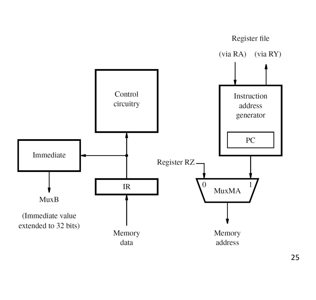
IR sits next to the control circuitry. Inputs:
- Memory data (from the processor-memory interface), loads when IR_en is asserted by the control unit.
Outputs:
- To control circuitry (opcode and function fields).
- To immediate generator (extracts and sign-extends the immediate field for use in MuxB).
- To register file (rs, rt, rd fields → addresses A, B, C).
The IR_en control signal goes high only during the Fetch stage when the memory transfer is complete (typically IR_en = T1 · MFC where T1 marks Fetch and MFC is “memory function complete”).