Day-to-day operation is one loop: fetch an instruction from memory, decode it, fetch any operands, execute, store the result, repeat. The control unit sequences each step with control signals; the datapath moves the bits.
What follows is that loop for a short instruction sequence, with enough detail to see the role of each component. For the cycle-accurate version see Instruction execution cycle.
Three example instructions
Take a typical RISC sequence:
Load   R2, LOC
Load   R3, LOC2
Add    R4, R2, R3
Store  R4, RESULT
Each instruction does one specific thing:
Load R2, LOC— read the word at memory location LOC into register R2. The original LOC contents stay in memory; whatever was previously in R2 is overwritten.Add R4, R2, R3— read R2 and R3, send them to the ALU, put their sum in R4. R2 and R3 unchanged.Store R4, RESULT— write the contents of R4 into memory at RESULT. R4 unchanged.
Pattern: arithmetic happens between registers, loads bring data into registers, stores send results back. This is the load/store architecture convention used by RISC ISAs. Memory is never the direct operand of an arithmetic instruction.
The hardware
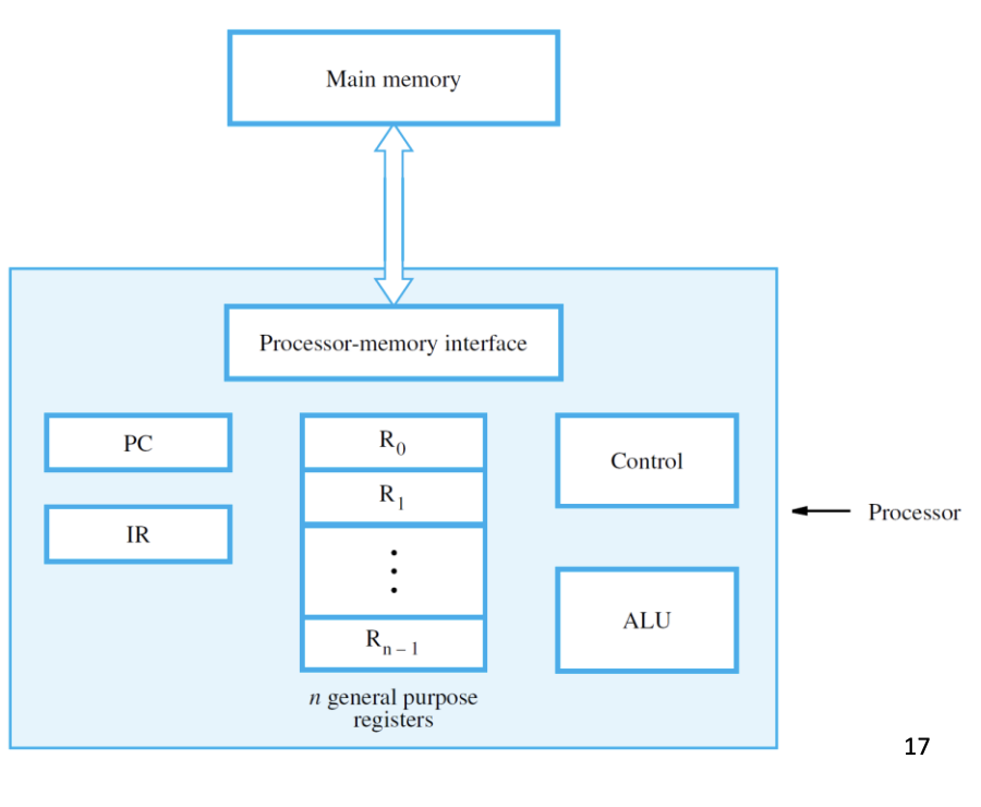
Inside the processor:
- Program counter (PC) — holds the address of the next instruction.
- Instruction register (IR) — holds the instruction currently being decoded.
- General-purpose registers R0..Rn-1 — hold operands and results.
- ALU — does the math.
- Control circuitry — generates the timing signals that govern everything.
- Processor-memory interface — handles the address bus, data bus, and Read/Write control lines.
How the example sequence runs
Walking through Load R2, LOC:
- Processor sends PC’s value to memory with Read asserted (instruction fetch).
- Memory returns the encoded
Load R2, LOCinstruction. It lands in IR. - PC is incremented (by 4 in a 32-bit RISC) so it points to the next instruction.
- Control unit decodes IR. Sees: load to R2 from memory at address LOC.
- Address LOC goes out on the address bus, Read asserted.
- Memory returns the word at LOC. The datapath routes it into R2.
The next instruction (Load R3, LOC2) repeats the pattern. Then Add R4, R2, R3:
- Fetch as before.
- Decode: ALU operation, two register sources, one register destination.
- R2 and R3 contents pass through the datapath into the ALU.
- ALU produces R2 + R3.
- Datapath writes the result into R4. No memory access this time.
Then Store R4, RESULT:
- Fetch.
- Decode: write R4 to memory at RESULT.
- Address RESULT goes on the address bus, R4 contents go on the data bus, Write is asserted.
- Memory updates that location.
Loading the program
Before any of this can happen, the program itself has to be in memory. The loader (part of the OS) reads the executable from secondary storage and copies it into RAM, then sets PC to the program’s first instruction address. Execution begins.
Interruptions
An external device sometimes needs urgent attention: a key was pressed, a packet arrived. It signals an interrupt. The processor pauses what it’s doing, saves enough state (PC, registers, control flags) to resume later, runs the interrupt service routine for the device, restores state, and resumes the original program where it left off.
This is the lightest form of context switch, and the program never knows it was interrupted. Heavier context switches (for OS multitasking) save more state, but the mechanism is the same.
What sits on top
The rest of ISA design (addressing modes, branch instructions, the stack, subroutines, I/O) all sits on this fetch/decode/execute loop. The loop runs for every instruction, billions of times per second.