The hardware datapath is the physical circuitry data flows through during instruction execution. It contains the register file, the ALU, multiplexers that route operands, and inter-stage registers (RA, RB, RZ, RY, RM) that hold values between the stages of the execution cycle.
The datapath is the “what moves where” of the processor. The control unit is the “when and why.”
The five stages mapped to hardware
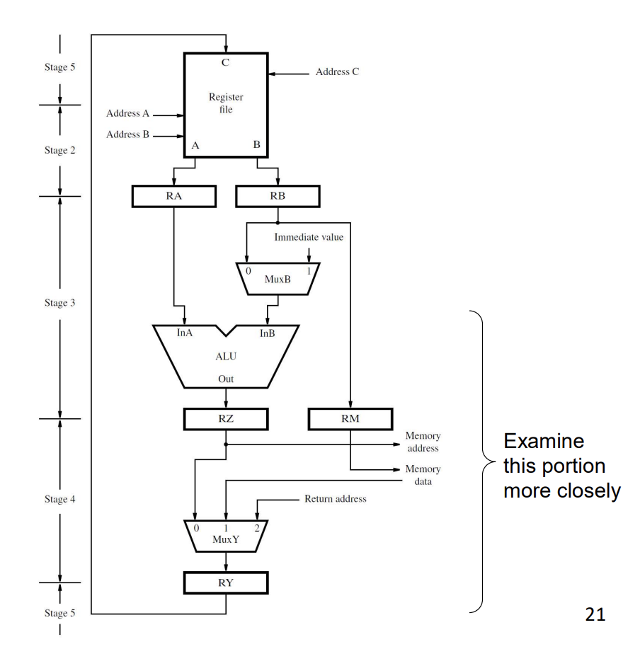
Read top to bottom for the standard 5-stage flow:
- Stage 5 (Writeback), at the top: the register file’s write port (C input) writes to a destination register based on RY.
- Stage 2 (Decode/Read): register file’s read ports A and B drive the next-stage registers RA and RB.
- Stage 3 (Execute): RA and RB feed the ALU. RB also goes through MuxB which can substitute an immediate value (for
addi, etc.). The ALU result lands in RZ. RB’s value is also latched into RM in case of a Store. - Stage 4 (Memory): RZ goes to memory as either an address (for Load/Store) or just passes through. RM goes to memory as data (for Store). Memory data comes back as input to MuxY.
- Back to Stage 5: MuxY picks among ALU result (RZ), memory data, and return address. Its output latches into RY for the writeback in stage 5.
Inter-stage registers
The capital-letter registers between stages are physical D-flip-flops:
- RA, RB: hold register-file outputs at the end of Decode.
- RZ: holds the ALU output at the end of Execute.
- RM: holds the value to be stored to memory at the end of Execute (for Store instructions).
- RY: holds the value to be written back to the register file, set during Memory or Execute depending on the instruction.
These registers exist so each stage can do its work in one cycle and hand off cleanly to the next stage. They’re invisible to the programmer.
Multiplexers
Several muxes route data based on instruction type:
- MuxB: picks between RB and a sign-extended immediate as the second ALU input.
- MuxY: picks among RZ (ALU result), memory data, or return address (for Call) as the value to write back.
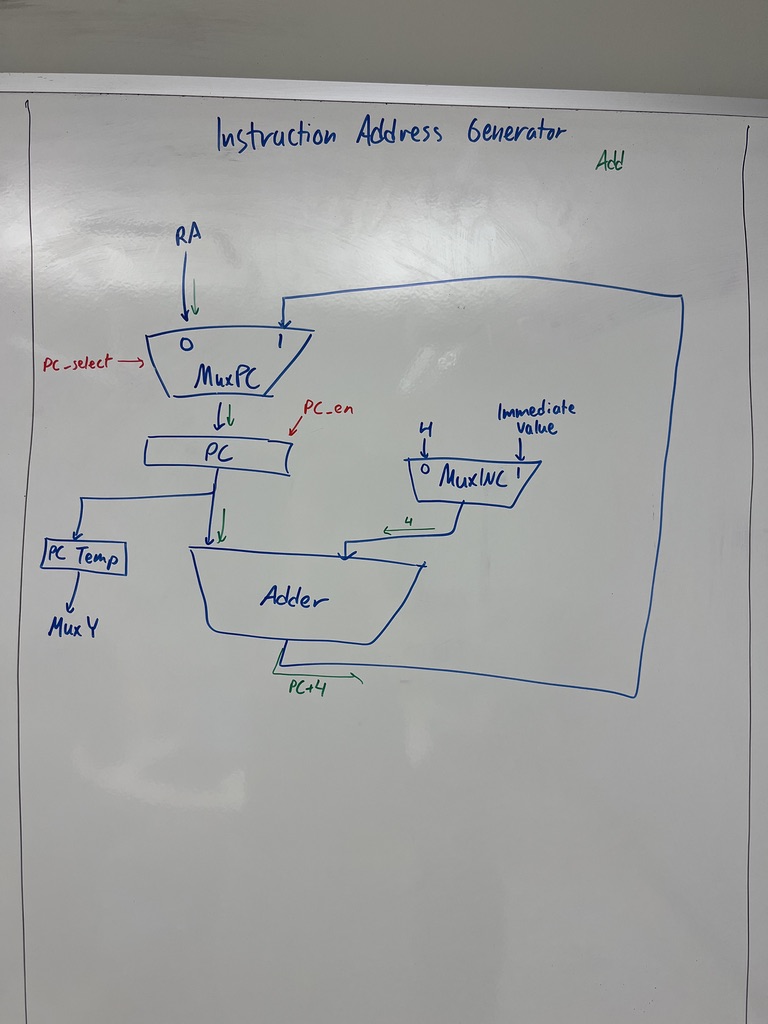
- MuxPC: picks the next PC value: PC + 4 (sequential), branch target (offset), or RA (return).
- MuxMA: picks the memory address: RZ (data access) or PC-derived (instruction fetch).
Each mux has a select signal driven by the control unit.
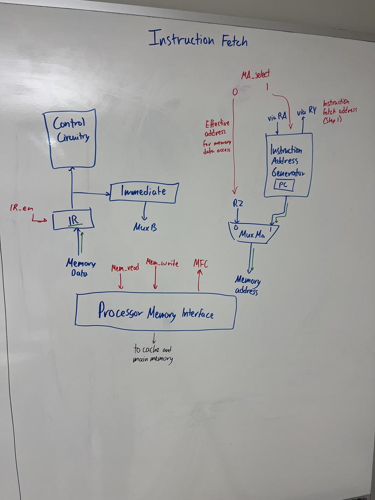
Instruction fetch hardware
The fetch path is somewhat separate from the data path:
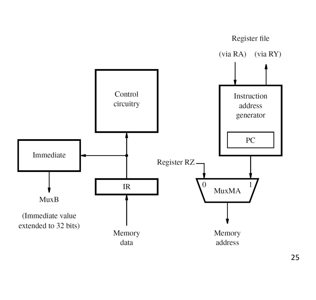
Components:
- PC in the instruction address generator.
- MuxMA chooses between the data-access address (RZ) and the instruction-fetch address (PC-based).
- Memory data comes in from the processor-memory interface, into the IR (during a fetch) or to MuxY (during a load).
- IR holds the current instruction.
- Immediate generator extracts and sign-extends the immediate field of IR for MuxB.
Instruction address generator
The PC’s update logic:
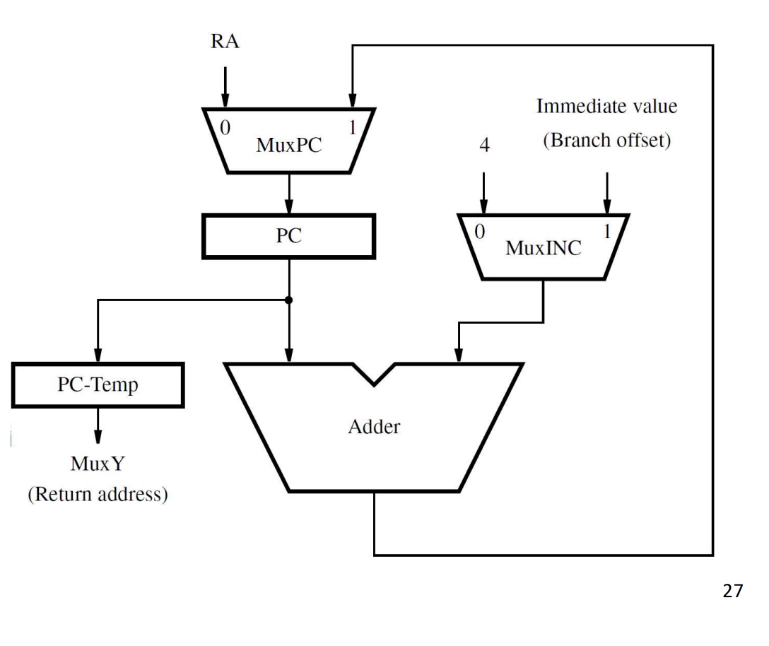
- MuxPC picks PC’s next value: either MuxINC’s output (PC + 4 or PC + branch offset for sequential/branch) or RA (for
ret). - MuxINC picks the increment: 4 (normal) or the branch immediate (branch).
- PC-Temp holds the saved PC during a Call instruction (so it can be moved to MuxY → RY → link register).
With control signals labelled
Same three diagrams, redrawn with the control signals (RF_write, IR_en, PC_en, PC_select, etc.) annotated on each enable and mux-select line, so you can see which signals fire in which stage. For what each signal does and the Boolean equations that produce it, see Control unit and control signals.
Putting it together
Tracing Subtract R5, R4, R3 through the datapath (where R4 = 0x8765, R3 = 0x4321):
- Cycle 1 (Fetch): PC sent to memory, instruction loads into IR, PC ← PC + 4.
- Cycle 2 (Decode): Register file reads R4 and R3. RA ← 0x8765, RB ← 0x4321.
- Cycle 3 (Execute): ALU subtracts. RZ ← 0x8765 − 0x4321 = 0x4444.
- Cycle 4 (Memory): No memory access. RY ← RZ = 0x4444.
- Cycle 5 (Writeback): Register file writes RY (0x4444) into R5.
The datapath has done one instruction in 5 cycles. With pipelining, the same hardware can have 5 instructions in flight at once, completing one per cycle.