The ideal op-amp model is five simplifying assumptions that make op-amp circuits solvable by hand. A real op-amp is close enough that the model predicts behaviour to a fraction of a percent, so we use it for almost all design and only reach for corrections (Real op-amp imperfections) when precision demands it.
The five idealisations:
- Infinite input impedance. No current flows into either input terminal. The inputs sense voltage but draw nothing.
- Zero output impedance. The output behaves as an ideal voltage source: whatever load is hung on , the voltage does not sag.
- Infinite open-loop gain . The differential gain is so large that, in any circuit using Negative feedback, the input difference must be near zero, otherwise would be impossibly huge.
- Zero common-mode gain, equivalently infinite Common-mode rejection ratio. Any signal common to both inputs is rejected; the device responds only to the difference.
- Infinite bandwidth. does not depend on frequency. (In reality rolls off above a few hertz; that’s Open-loop gain frequency dependence, treated under Real op-amp imperfections.)
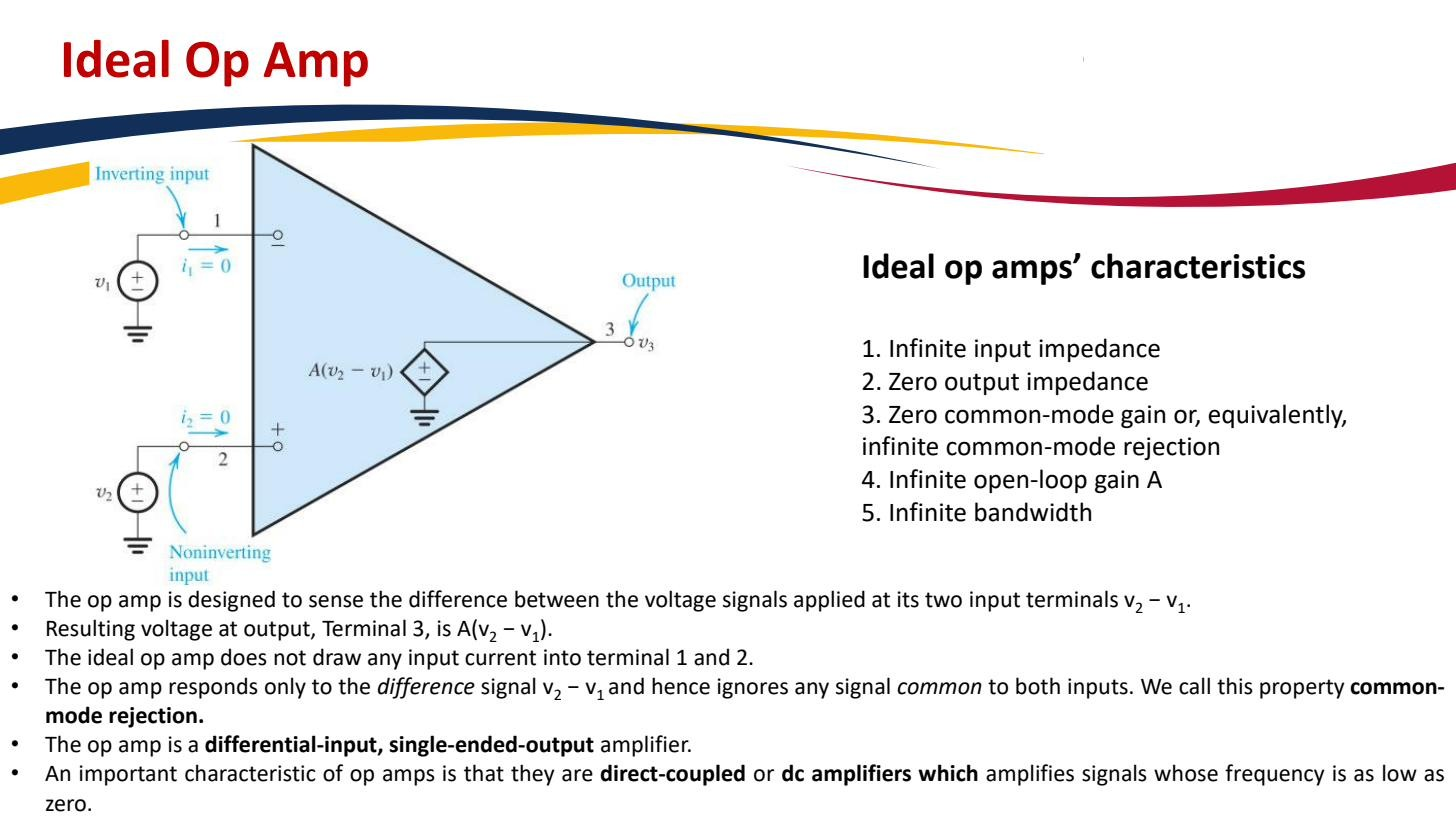 The five ideal-op-amp characteristics.
The two golden rules
For analysis the whole model collapses into two statements. These are the only tools you need to solve any op-amp circuit that uses negative feedback.
Golden rule 1 — no current into the inputs. Infinite input impedance restated for circuit analysis: . Any current arriving at an input node has to go somewhere else, into a feedback resistor typically. This is what lets you write KCL at the input node and ignore the op-amp as a current sink.
Golden rule 2 — the inputs are equal. In a negative-feedback configuration, . Reasoning: the output is with . For to be a finite voltage (it has to be, it’s pinned between the rails), the difference must be . The op-amp adjusts its own output through the feedback path until its two inputs are equal. It does whatever it takes. This forced equality, with no physical wire between the inputs, is the Virtual short and virtual ground.
Every circuit in the inverting/non-inverting family, the Summing amplifier, Difference amplifier, Op-amp integrator and Op-amp differentiator is derived by applying these two rules with KCL at the inverting node. Memorise them; the rest is algebra.