A peak rectifier is any Rectifier with a large capacitor in parallel with the load. The capacitor charges up to the peak of the rectified waveform and then holds the output near that peak between peaks, turning the lumpy rectifier output into something close to DC with only a small Ripple voltage. The capacitor goes by several names (smoothing capacitor, filter capacitor, reservoir capacitor), all the same component doing the same job.
How it smooths
Start from a bare rectifier whose output is a train of half-sinusoid humps. Add a capacitor across the load .
- Near a peak: the rectified voltage is rising toward and is higher than the capacitor voltage, so the diode is forward biased. Current flows through the diode and rapidly charges up to (almost) the peak, minus the relevant diode drop(s).
- After the peak: the rectified input falls back toward zero. Once it drops below the capacitor voltage, the diode becomes reverse biased and disconnects the source from the load. The capacitor cannot discharge back through the diode, so it can only discharge through the load resistance .
- Discharge condition: if the discharge time constant is much longer than the input period , the capacitor barely droops before the next peak arrives to top it up. The output then sits close to all the time, with a small sawtooth wobble (the Ripple voltage) instead of full half-sinusoid humps.
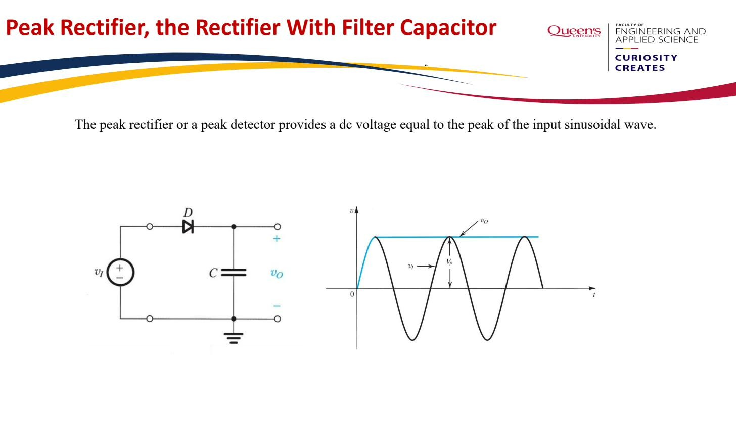 Capacitor charges to at peaks, discharges slowly through the load. Approximately DC with small ripple.
So the output is no longer the rectifier’s average ( or , see DC value of a rectified waveform); it sits near the peak . That’s the whole point: far more voltage and far less variation.
The hidden cost: short conduction, big diode current
Because the capacitor holds the output near , the rectified input only exceeds the output for a brief moment around each peak. The diode is off most of the cycle and conducts only in a short burst near the top, a small Conduction angle.
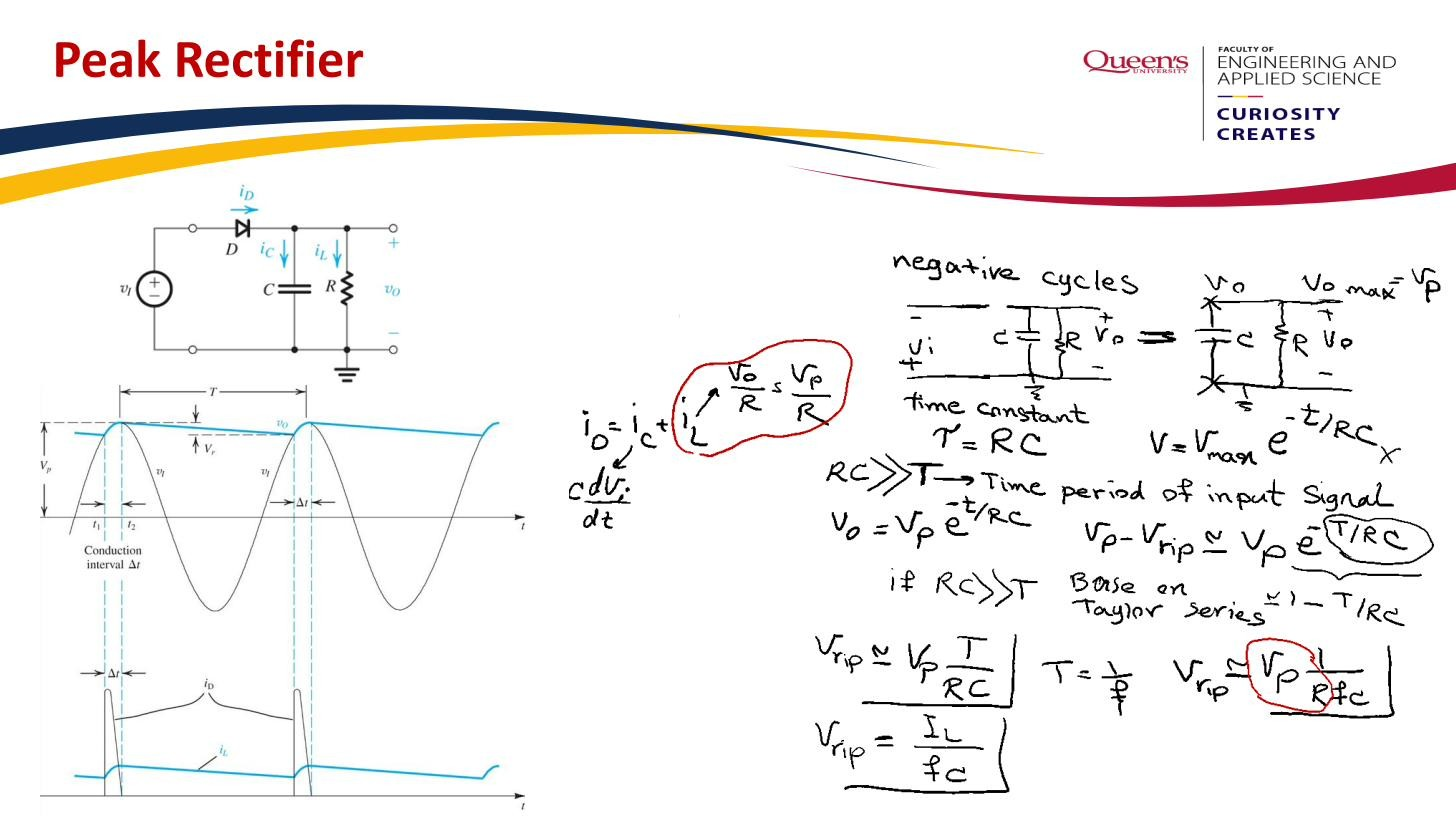 The diode conducts only briefly near each peak; the rest of the cycle the load draws from the capacitor.
During that short burst the diode must replace all the charge the load drained from the capacitor over the entire cycle. Charge delivered in a short time means a large current: the peak and average diode currents are many times the DC load current . This sets the diode’s current rating, covered quantitatively in Conduction angle. The peak rectifier is the standard smoothing stage of every linear DC power supply.