The half-wave rectifier is the simplest Rectifier: one Diode in series with the load. It passes the half-cycles of one polarity straight through and blocks the other polarity entirely, so the output is a series of one-sided humps with flat gaps between them.
Ideal-diode behaviour
With an Ideal diode model the analysis is two states. When the input has the polarity that forward-biases the diode, the diode is a short and the full input appears across the load: . When has the opposite polarity, the diode is an open circuit, no current flows, and the output is zero: . The transfer characteristic is two straight pieces: a unity-slope line through the origin for the conducting polarity, flat at zero for the other.
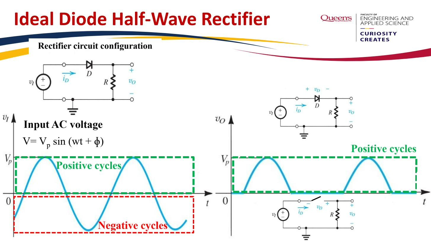 Positive cycles pass, negative blocked: positive humps with gaps.
The slide draws the diode with its cathode toward the source (anode toward the load), so this circuit passes the negative half-cycles and clips the positive ones: when and otherwise. Flipping the diode the other way (the more common textbook convention) passes the positive half instead. Same physics; which half survives just depends on which way the diode points.
![]() Ideal half-wave rectifier: circuit, output waveform, transfer characteristic (slide passes the negative half-cycle).
Ideal half-wave rectifier: circuit, output waveform, transfer characteristic (slide passes the negative half-cycle).
CVD behaviour
The real diode does not turn on until it has about 0.7 V across it, so with the Constant-voltage-drop model the output is
with V. The conduction threshold is shifted away from zero by , and the surviving peak is reduced to . The transfer characteristic still has unity slope when conducting, just offset by .
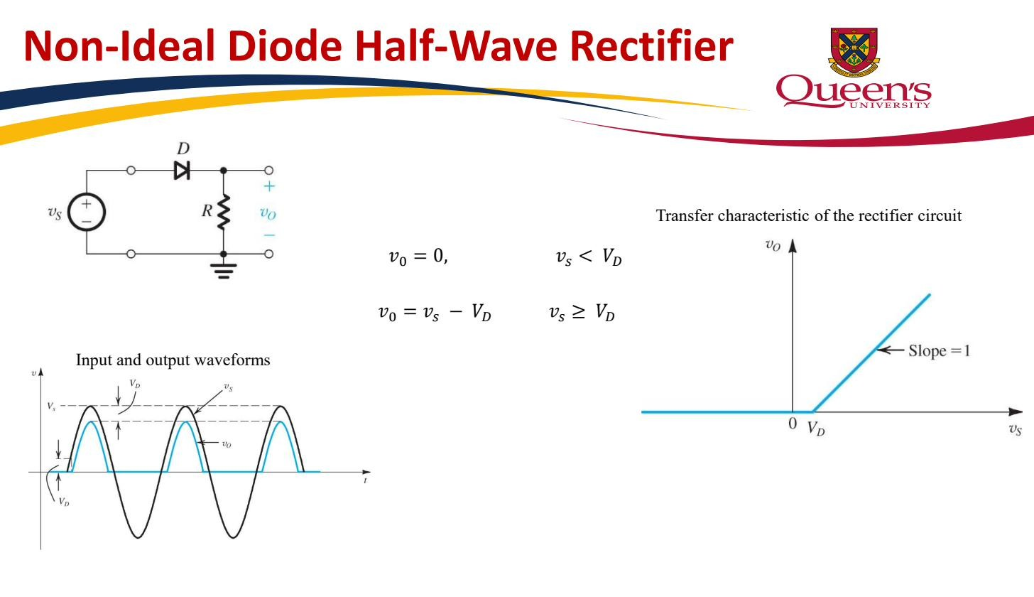 CVD model: for , for ; the diode drop lowers the peak.
Two practical numbers
The Peak inverse voltage is the worst-case reverse voltage the diode must survive. When the input is at its blocked-polarity peak (magnitude ) the diode is off, no current flows so there is no drop across the load, and the entire input swings across the diode: . The diode’s reverse voltage rating must exceed this.
The DC component is the time-average of the lumpy output. For an ideal half-wave-rectified sinusoid of peak (half-cycles of a sine averaged over a full period) the average is . The derivation and the full-wave counterpart are in DC value of a rectified waveform. That low, lumpy average is why a half-wave rectifier alone is a poor DC source and almost always gets a smoothing capacitor.