A MOSFET (Metal-Oxide-Semiconductor Field-Effect Transistor) is the universal switch of digital electronics. It has three terminals (source, gate, drain) plus a body terminal usually tied to source or supply. Voltage on the gate controls whether current can flow between source and drain. The “metal-oxide-semiconductor” part names the gate stack: a metal (or polysilicon) electrode separated from the silicon channel by a thin oxide insulator.
There are two flavors based on the channel’s majority carrier: NMOS (electrons) and PMOS (holes). They have opposite turn-on conditions, which is what makes CMOS possible.
In digital logic the MOSFET behaves as an idealized voltage-controlled switch: closed when the right gate voltage is applied, open otherwise. The “field effect” in the name refers to how the gate voltage’s electric field induces (or doesn’t induce) a conducting channel beneath the oxide. The gate draws essentially no DC current (it’s capacitively coupled), which is why MOS logic dissipates almost no static power.
Symbols:
- NMOS: arrow pointing inward at the source, no bubble on the gate. On when gate is high.
- PMOS: arrow pointing outward, bubble on the gate. On when gate is low.
Source supplies carriers, drain collects them, controls. The supply voltage is conventionally written (drain supply) and ground .
The analog view (Electronics I)
The digital picture above treats the MOSFET as an ideal on/off switch, but it is really a four-terminal analog device: source (S), gate (G), drain (D), and body/substrate (B), the latter usually shorted to the source. It has three MOSFET regions of operation: cut-off (no channel, , the Threshold voltage), triode (channel formed end-to-end, acts as a gate-controlled resistor, the digital on-state), and saturation (channel pinched at the drain, ). Digital logic uses cut-off and triode; analog circuits bias the device in saturation, where the MOSFET square-law makes it a voltage-controlled current source. That turns the MOSFET from a switch into a saturation-region amplifier, the basis of all analog MOS design.
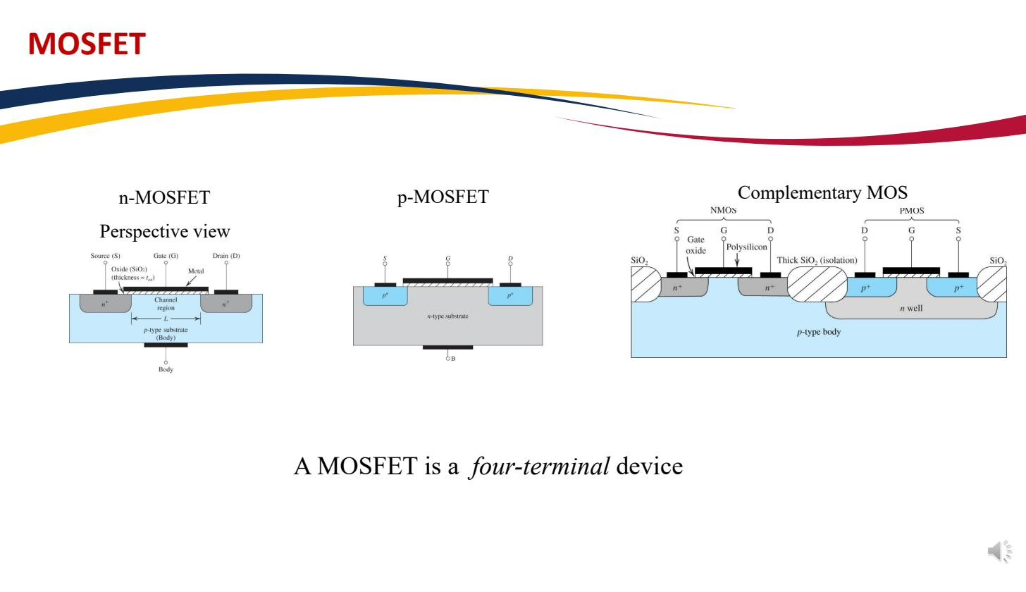 The MOSFET is a four-terminal device; n-MOSFET in a p-substrate (n+ S/D), p-MOSFET the complement.
The most common schematic symbols put an arrow on the body (or source) terminal: pointing inward for an n-MOSFET, outward for a p-MOSFET. When the body is tied to the source (the usual case), a simplified three-terminal symbol is used with the arrow on the source.
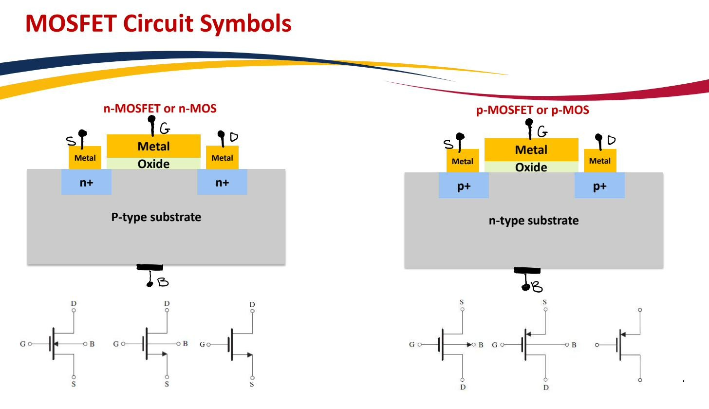 n-MOSFET (arrow inward) vs p-MOSFET (arrow outward); simplified 3-terminal symbols when body=source.