A lowpass filter passes signal frequencies near DC and attenuates high frequencies. The simplest first-order lowpass has transfer function
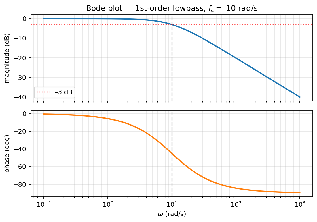 Bode plot of a first-order lowpass with corner rad/s: −20 dB/decade rolloff past , phase from 0° to −90°.
where is the cutoff frequency in rad/s. (Filter transfer functions are usually written in ω-form; the formula sheet’s filter tables follow this convention.)
Behavior
- At DC (): . The signal passes unattenuated.
- As : . High frequencies are blocked.
- At : . Magnitude has dropped to about , which is a drop. So is the half-power cutoff.
This is the canonical first-order lowpass response. The RC lowpass we keep running into has exactly this form, with .
Pole-zero structure
One pole at on the negative real axis. No zeros. The pole’s location in the left half-plane tells you the filter is stable; its distance from the imaginary axis () determines how broadly the filter passes frequencies.
Bode plot
Asymptotic magnitude (in dB): flat at for , then dropping at for . The true curve is at , transitioning smoothly between the two asymptotes.
Phase: starts at at low frequencies, transitions through at , and asymptotes to at high frequencies. The transition spans two decades, from to . See Bode plot for the construction rules.
Impulse response
The inverse Laplace of is , a decaying exponential with time constant . So the filter’s “memory” persists for about seconds.
Step response
The step response is the integral of the impulse response: . The familiar RC step response: exponential approach to a final value of 1.
Higher-order lowpasses
A second-order lowpass adds another pole, doubling the high-frequency rolloff to . With complex-conjugate poles you can get a sharper transition near the cutoff at the cost of a peak just before rolling off.
Order- lowpasses have poles total and roll off at past cutoff. Higher order means sharper cutoff but more complex implementation and more phase distortion.
Where it’s used
- Audio: remove hiss above the audible band.
- Anti-aliasing before sampling — protects against high-frequency content aliasing into the band.
- Smoothing of measurement signals (sensor data, control feedback).
- “Integrator” approximation — over a band well above , the magnitude is , which is like a integrator.
Circuit realisation
The concrete first-order lowpass in electronics is the RC lowpass filter: a series resistor feeding a shunt capacitor, output across the capacitor, with Cutoff frequency and a rolloff above it. The capacitor is an open at DC (signal passes) and a short at high frequency (output grounded), which is the physical mechanism behind this transfer function.