An RC lowpass filter is a resistor in series with the signal path and a capacitor from the output node to ground, output taken across the capacitor. It passes low frequencies almost unchanged and increasingly attenuates high ones. The canonical Lowpass filter.
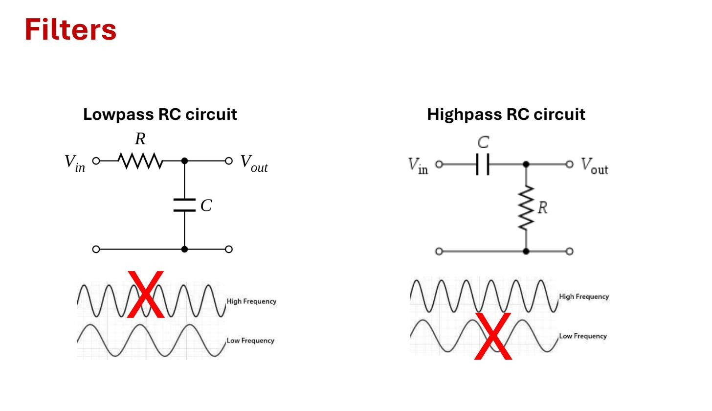 The two RC filters: a series resistor with a shunt capacitor forms a lowpass; swapping the two gives a highpass.
Intuition: the capacitor as a frequency-dependent resistor
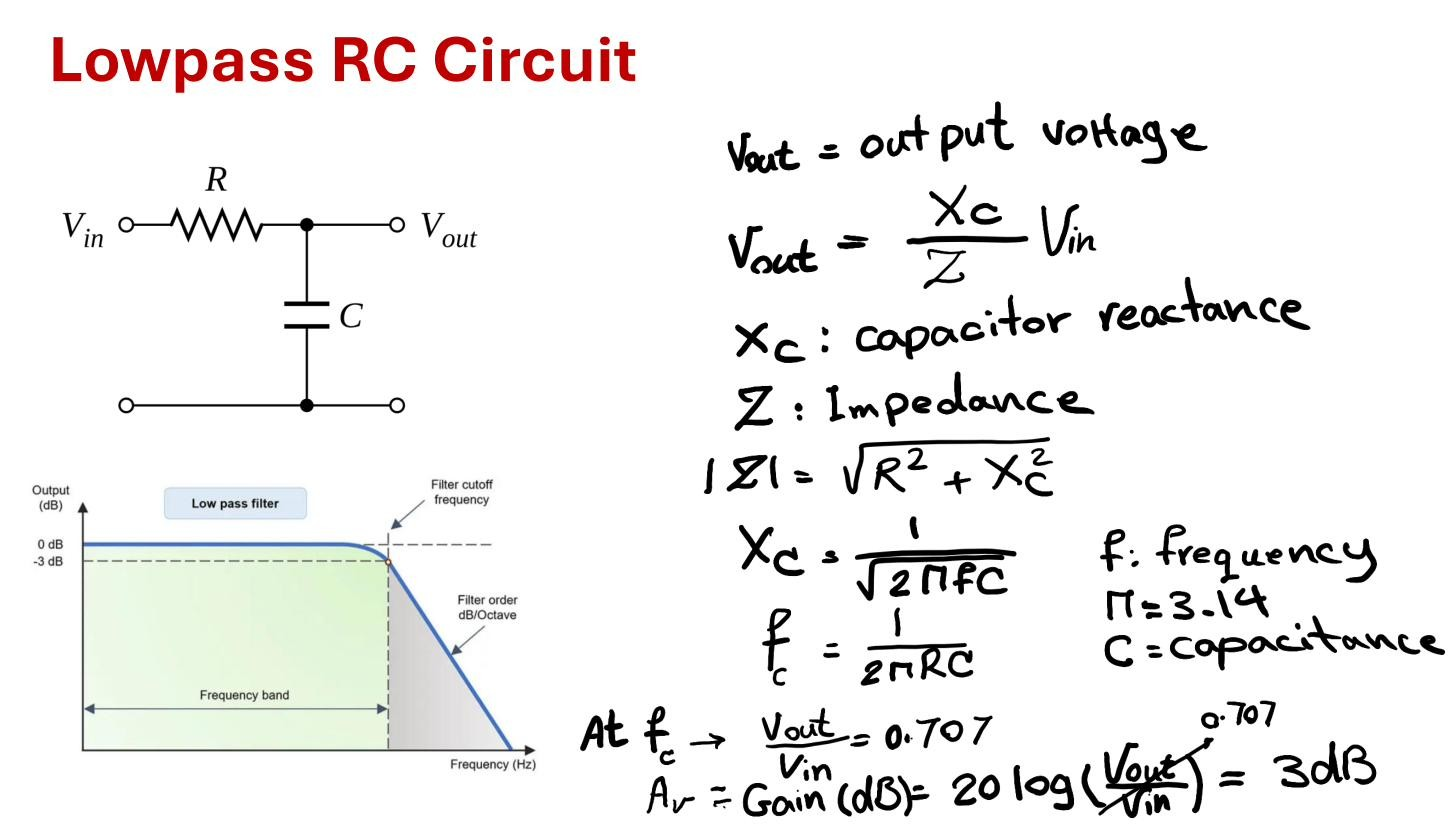
The behaviour follows from how a capacitor’s impedance changes with frequency (Capacitive reactance). The impedance of the capacitor is
where is the angular frequency, the capacitance, and . Its magnitude is .
- Low frequency (): . The capacitor looks like an open circuit. No current flows through , so no voltage drops across , and all of appears at the output. Gain .
- High frequency (): . The capacitor looks like a short to ground. It clamps the output node near zero regardless of the input. Gain .
In between there’s a frequency where equals , the crossover between “passes” and “blocks”. That’s the Cutoff frequency.
(A handwritten note on the slide writes with a stray square root. Slide typo; the correct reactance magnitude is , no square root.)
Transfer function
The circuit is a voltage divider between and with the output across . The Transfer function is the ratio of output phasor to input phasor:
Multiply top and bottom by to clear the fraction:
Check the limits against the intuition above: at , (passes). As , (blocks). The magnitude is
Cutoff frequency
The corner of the response is where the magnitude has fallen to of its low-frequency value, the −3 dB point (half power). Set :
with in rad/s and in Hz. At the capacitor’s reactance exactly equals , the output is , and the phase is . Worked example: with and ,
Signals well below pass; signals well above it are attenuated.
Rolloff: 20 dB/decade
Far above , , so : magnitude inversely proportional to frequency. Every factor-of-10 increase in frequency divides the output by 10, i.e. drops it by . So above the cutoff the response rolls off at a constant , the signature slope of a first-order filter on a Bode plot.
Where you meet it
This network is everywhere, often without being labelled a filter. The parasitic capacitance at the output of an amplifier stage forms an RC lowpass with the stage’s output resistance, and that’s what limits the amplifier’s high-frequency bandwidth. Swap and and you get the RC highpass filter, the same circuit used as a Coupling capacitor between stages.
 The lowpass RC filter: series then shunt , across ; dB at , then dB/decade.