An RC highpass filter is the RC lowpass with its two components swapped: a capacitor in series with the signal path and a resistor from the output to ground, output taken across . It blocks low-frequency (and DC) signals and passes high-frequency ones, the canonical Highpass filter.
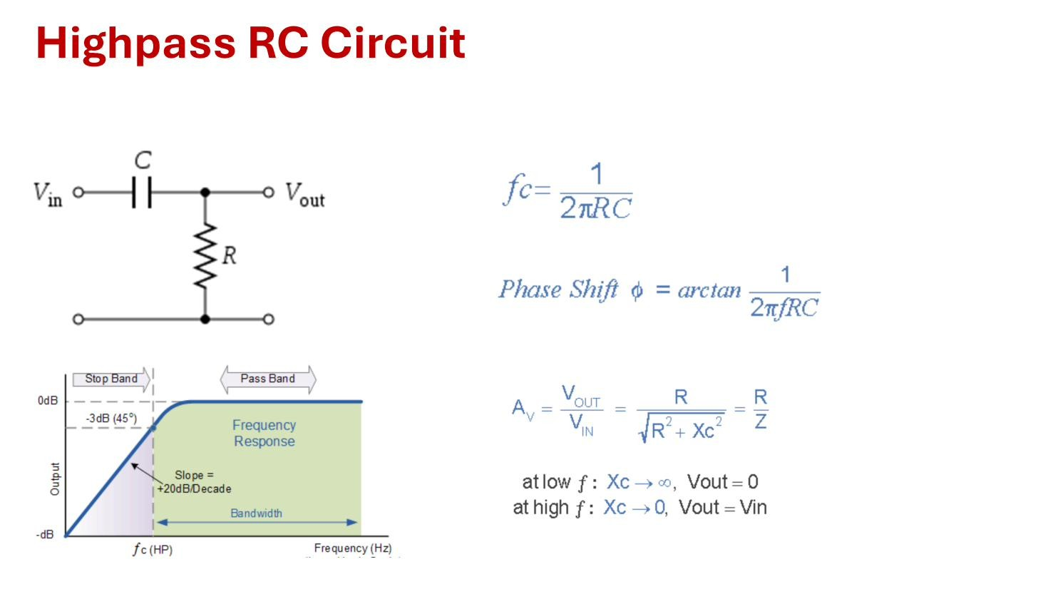 The highpass RC filter: series capacitor, shunt , across ; rises at dB/decade below .
Intuition
Reuse the Capacitive reactance picture, but now the capacitor is in series between input and output rather than shunting the output to ground.
- Low frequency (): . The series capacitor looks like an open circuit and disconnects the input from the output, so . It blocks DC completely ( gives infinite impedance).
- High frequency (): . The series capacitor looks like a wire, so . The signal passes through unimpeded.
The behaviour is the exact mirror of the lowpass: low frequencies blocked, high frequencies passed.
Transfer function — derive it
Again a voltage divider, but now the output is across and the series element is :
Multiply numerator and denominator by :
Check the limits: at , (blocked); as , the terms dominate and (passed). The magnitude is
Same cutoff, opposite slope
The corner is at the same frequency as the lowpass. It depends only on and , not on which one is in series:
At the magnitude is (the −3 dB point). The difference from the lowpass is the direction of the slope: below the response rises at (every decade lower in frequency cuts the output by a factor of 10), then flattens to unity above . The lowpass rolls off above instead.
Phase
The numerator has a factor of , which contributes , and the denominator subtracts a frequency-dependent angle. The net phase is
At very low frequency the argument blows up and (the output leads the input by nearly a quarter cycle). Far above the argument and (output in phase with input). At exactly , .
This is a coupling capacitor
Every multistage amplifier puts a series capacitor between stages to pass the AC signal while blocking the DC bias of one stage from disturbing the next. That series capacitor, together with the input resistance it sees, is an RC highpass (see Coupling capacitor). Its cutoff sets the low end of the amplifier’s useful frequency range: signals below it are attenuated, so coupling capacitors are sized to put safely below the lowest frequency of interest.