A D flip-flop is an edge-triggered storage element that captures its (“data”) input on a clock edge and holds it until the next edge. Output matches whatever was at the moment of the triggering edge: no transparency, no glitches between edges.
The “edge-triggered” part is what distinguishes it from a gated D latch. A latch is transparent during the entire active level of the clock; a flip-flop only samples at the transition.
| Clk edge | ||
|---|---|---|
| no edge | x | (hold) |
| ↑ | 0 | 0 |
| ↑ | 1 | 1 |
Most synchronous designs use positive-edge triggered D flip-flops, which sample on the rising edge ( transition) of the clock. Negative-edge triggered ones exist and behave the same way on the falling edge.
Leader-follower (master-slave) construction
The classic implementation is two gated D latches in series, with opposite-phase clocks:
- The leader (master) latch loads when Clk , capturing .
- The follower (slave) latch loads when Clk , copying the leader’s value to .
When Clk transitions , the leader stops sampling (its input is locked) and the follower starts sampling (it copies whatever the leader was holding). The output thus changes only at the negative edge.
For a positive-edge triggered flip-flop, invert the clock fed to the leader: the leader now loads when Clk and the follower transfers when Clk . So the visible output transition lines up with the rising edge of the original Clk. The construction is otherwise unchanged.
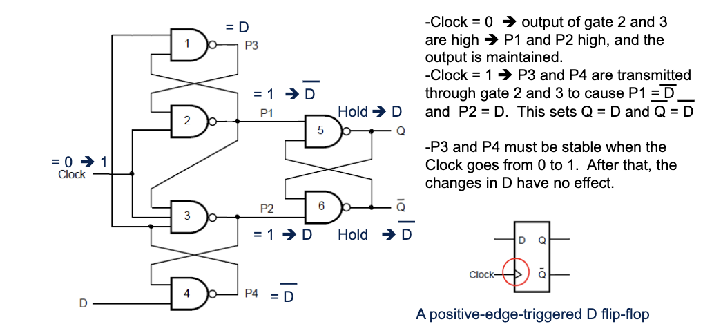
True edge-triggered design
The standard textbook positive-edge-triggered D flip-flop is built from six NAND gates arranged as three interconnected SR latches: two input-stage latches that share the clock, plus one output-stage latch. The input stage decodes whether D was high or low at the rising edge of the clock; the output latch holds that value until the next edge.
When the clock is low, the input-stage outputs are forced to logic 1 regardless of D, so the output latch holds its previous value. On the rising edge of the clock, exactly one of the input latches drops to 0 (the upper one if D=1, the lower one if D=0) and that pulse sets or resets the output latch. After the edge, both inputs are stable again and the output is locked.
This is more compact and faster than a master-slave construction (six NAND gates vs. roughly eleven), and behaves identically from the outside.
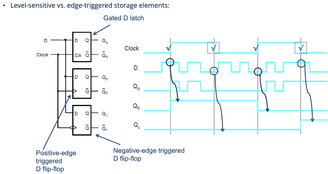
Compare the three storage element types in the timing diagram:
- — gated D latch. Transparent when clock is high; follows every change in during that time.
- — positive-edge triggered D flip-flop. samples at each rising clock edge, ignoring everything else.
- — negative-edge triggered D flip-flop. Same, but on falling edges.
With the latch you can see glitching through to during clock-high; with the flip-flops you only see one clean update per clock period.
Asynchronous Clear and Preset
D flip-flops typically have two extra inputs, Clear and Preset, that override the normal D-input/clock behavior:
- Clear (or Reset) forces .
- Preset (or Set) forces .
Both are typically asynchronous — they take effect immediately, independent of the clock. Often drawn as active-low inputs (with a bar over the name: , ).
![]()
Clear matters at power-on: without it, your flip-flops come up with random values, and the circuit’s behavior is undefined until something definite is loaded. Tie an asynchronous Clear to a power-on reset signal and the whole machine starts in a known state.
Don’t assert Clear and Preset simultaneously — same reason as the SR latch’s forbidden state.
If you want the clear to take effect only at the next clock edge, use a synchronous clear instead, typically by AND-gating the Clear signal with the D input:
![]()
Now the flip-flop sees , which forces when Clear is asserted but only takes effect at the next clock edge. Synchronous clear is preferred when timing predictability matters more than instant reset.
Why D is the standard
Among all flip-flop types (D, T, JK, plus older SR), D is the simplest and the most common in modern designs. It’s:
- The cleanest model: next cycle = this cycle.
- The easiest to use in VHDL (just write
Q <= Din a clocked process). - The native primitive in most FPGA logic blocks. Modern slices/ALMs typically pair 2 LUTs with 2 D flip-flops, not one-LUT-one-FF.
- The cheapest in CMOS for the same functionality.
For toggling counters and certain compact logic, T or JK can be slightly more economical, but the difference is small enough that most designers default to D and let synthesis handle the optimization.