A state equation (or transition equation) is a Boolean function expressing the next state of a Sequential circuit in terms of the current state and the inputs.
If a flip-flop holds bit of the state, its state equation is the Boolean function . With one equation per flip-flop, you have a complete description of the FSM’s transition behavior.
Equivalent to a State table in algebraic rather than tabular form. State equations are typically derived from the state table by reading off each entry of the next-state column and minimizing with a Karnaugh Map.
Example
For a circuit with state bits and , output , and input , with D flip-flops (where next-state value):
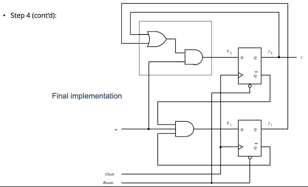
The state equations might look like:
And the output equation:
The equations describe what each flip-flop’s input should compute. The first equation says “the next is when and either or is currently .” The second says “the next is when the current is and .”
Where state equations come from
Two paths:
-
From the state table. For each next-state bit, write down the rows where that bit becomes , then minimize with a K-map to get a compact Boolean expression.
-
Directly from a state diagram. For each transition from state to state on input , the bits of contribute terms to the state equations.
For D flip-flops, the state equation is the input equation, . For T flip-flops, you’d derive a input by XORing the current and next states. For JK, use the JK excitation table to find which values produce each desired transition.
Once you have state equations, the implementation is direct: each input becomes a combinational circuit that computes its equation from the state outputs and the inputs.