A sequence detector is a finite state machine that watches a serial input bit by bit and asserts an output when it sees a target pattern. The walkthrough below uses one as a worked example for the standard FSM design flow, which works for any FSM, not only sequence detection.
The target: detect two or more consecutive s on input . Once the input has been for at least two consecutive cycles, output should be .
The standard FSM design steps
- Obtain circuit specification — what should the circuit do?
- Derive a State diagram — graphical representation of states and transitions.
- Create a State table — tabular form of the diagram.
- Minimize states (see State Reduction).
- Perform State Assignment — assign binary codes to states.
- Choose a flip-flop type (D, T, or JK).
- Derive next-state logic — Boolean expressions for the flip-flop inputs.
- Derive output logic — Boolean expressions for the outputs.
- Implement the circuit — draw the final schematic.
Every FSM you build follows the same steps; only the specifics of each step change.
The walkthrough below runs those nine steps for this sequence detector. Step 1 (specification) is the prose paragraph above. Step 4 (state reduction) is skipped, since the three states identified are already minimal. The remaining steps map onto the section headers:
| 9-step | Section heading below |
|---|---|
| 2 | State diagram |
| 3 | State table |
| 5 | State assignment |
| 6, 7, 8 | Choose flip-flop type and derive logic |
| 9 | Final implementation |
Step 2 — State diagram
Three states are needed: A (no recent 1s, the reset state), B (just saw one 1), and C (seen two consecutive 1s, output asserted).
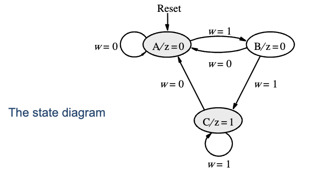
Reading: from A on input 0 stay; on input 1 go to B. From B on 0 return to A; on 1 advance to C. From C on 0 return to A; on 1 stay at C.
The output is associated with the state (Moore machine style): , , .
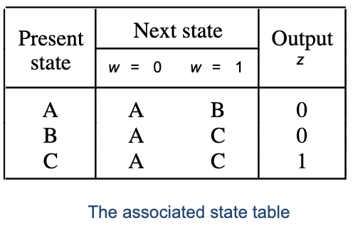
Step 3 — State table
| Present state | Next () | Next () | Output |
|---|---|---|---|
| A | A | B | 0 |
| B | A | C | 0 |
| C | A | C | 1 |
Step 5 — State assignment
Three states need 2 bits. Use as the state variables, encoded as:
| State | |
|---|---|
| A | 00 |
| B | 01 |
| C | 10 |
The fourth pattern is unused (a don’t-care).
Steps 6, 7, 8 — Choose flip-flop type and derive logic
Pick D flip-flops. They make the next-state logic the simplest, since next-state value directly.
State-assigned table:
| Present | Next () | Next () | |
|---|---|---|---|
| A: 00 | 00 | 01 | 0 |
| B: 01 | 00 | 10 | 0 |
| C: 10 | 00 | 10 | 1 |
| 11 (don’t care) | dd | dd | d |
Now build K-maps for , , and (each as a function of ).
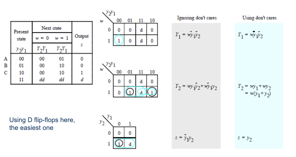
Reading off the K-maps (with don’t-cares used to enlarge groups):
The output happens to collapse to just : the second state bit is the output. That’s a consequence of the lucky state assignment.
The general structure of the FSM:
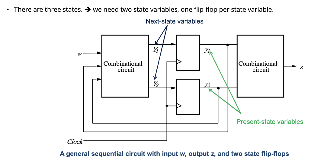
Two flip-flops hold the state; combinational logic feeds their D inputs from and the current state; another piece of combinational logic produces (here trivially: ).
Step 9 — Final implementation
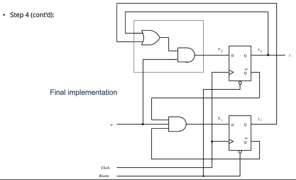
The completed circuit:
- : small AND chain.
- : OR followed by AND.
- : direct wire.
- Both flip-flops share a clock and a Resetn (asynchronous reset, active low) input that initializes the FSM to state A on power-up.
Lessons from the example
- A state diagram is the right place to start. Don’t go to logic until you’ve drawn one.
- State assignment matters. The choice made ; a different assignment would have required gates for .
- Don’t-cares from unused state codes can simplify the next-state logic substantially. Use them in K-map grouping.
- D flip-flops + K-map minimization is the simplest path. T or JK can save a gate or two but rarely justify the complexity.
The same nine-step flow applies to other FSM patterns (vending machine, traffic light, parity checker); only the state diagram changes.