A register is a group of flip-flops sharing a common clock, used to hold an -bit value. The simplest registers just store the value; more elaborate ones can also shift or load it.
A bare -bit register has data inputs , data outputs , and a single clock. On each rising clock edge, every is captured into its corresponding flip-flop and appears at .
Shift register
A shift register is a register whose contents shift by one position on each clock edge. The bit at position 0 either falls off the end or rotates around; new bits enter at one end (or both, depending on the design).
The simplest serial shift register chains flip-flops: each flip-flop’s output drives the next flip-flop’s input.
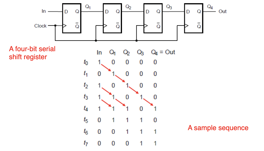
In a 4-bit version, an input bit goes into the first flip-flop, then on each clock cycle moves to the next, until it falls out the end after 4 cycles. The sample sequence in the diagram shows input “1011” entering the register over four clock cycles and gradually appearing at the output.
Uses:
- Serial-to-parallel conversion: feed bits in one at a time over cycles, then read all in parallel.
- Parallel-to-serial conversion: load bits in parallel, then shift them out one per cycle.
- Delay lines: delay a bit stream by cycles.
Parallel-access shift register
A parallel-access shift register combines shift and parallel-load functionality. A control signal (often labeled “Shift/Load”) picks which mode the register is in:
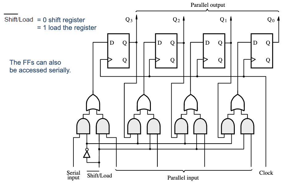
- Load mode (Shift/Load = 1): all inputs are sampled in parallel on the next clock edge.
- Shift mode (Shift/Load = 0): contents shift by one position, with a serial input feeding into the open end.
Each flip-flop is preceded by a small multiplexer that picks between “the parallel input” and “the previous flip-flop’s output” based on the mode bit. With this you can:
- Load 8 bits in one cycle.
- Shift them out serially over 8 cycles.
- Load new 8 bits.
- Repeat.
This is the data-path core of a UART transmitter: load the byte to send, then shift out one bit per baud period. A real UART also wraps the byte in framing bits (start, optional parity, one or two stop bits), so it’s a parallel-load shift register plus framing-control logic, not just the shift register alone.
Where registers fit
Registers are the everyday storage primitive in synchronous design. A processor’s register file is just an array of registers, each typically 32 or 64 bits wide. Pipeline stages between combinational logic blocks are registers. The state of an FSM is held in a register.
For storing many values addressed by index, you typically don’t use a giant register file but rather a memory (SRAM, DRAM) with separate read/write ports. Same idea, different physical implementation.