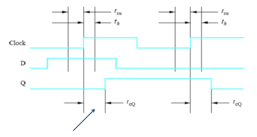
A flip-flop has timing constraints that determine the maximum clock frequency it can run at. Three numbers matter:
- (setup time) — how long the data input must be stable before the clock edge.
- (hold time) — how long the data must remain stable after the clock edge.
- (clock-to-Q delay) — how long after the clock edge before the new value is valid at the output.
If any of these is violated, the flip-flop may go metastable: its output settles to an unpredictable value (sometimes neither nor , oscillating for a while). Metastability is the chief enemy of synchronous design.
Why each matters
- ensures the data input is held stable long enough before the clock edge that the flip-flop’s internal cross-coupled feedback loop can be driven decisively into one of its two stable states (the basin or the basin) before the edge latches the value. Set up too late → the loop is still being pushed by the new input when the edge arrives, leaving it near its unstable equilibrium → metastability.
- ensures the input doesn’t change during the capture window. Held too short → the loop gets pushed back across its threshold before it has fully committed → metastability.
- is just propagation delay. Once the edge arrives, the new value isn’t instantly visible at the output.
The “RC charging” picture is a useful first sketch but doesn’t capture metastability. The deeper reason these constraints exist is the bistable feedback loop: like a ball balanced on a knife-edge, it needs a clear push and time to roll into one of the two basins. Bumping it just as the edge arrives can leave it teetering on the edge for an arbitrarily long time before it finally falls one way or the other.
Maximum clock frequency
In a synchronous circuit, after one flip-flop fires, the new value has to propagate through some combinational logic and arrive at the next flip-flop’s input before that flip-flop’s setup time. The minimum clock period is therefore:
where is the worst-case combinational delay between the source flip-flop’s and the destination flip-flop’s .
The maximum frequency is just the inverse:
Worked example
Given , , , and a per-gate delay of ns where is the number of inputs to the gate.
Assume the data path between two flip-flops contains a single 1-input NOT gate (gate delay = ).
You use the maximum for because timing analysis must hold for the worst case.
Hold-time check
The hold-time check uses the minimum delays. The destination flip-flop’s must not change for after the clock edge. The fastest path from source to destination is .
For the same example: . ✓ Hold time is satisfied.
If hold time fails, the new propagates through too quickly: the destination flip-flop sees the new value during its hold window instead of holding the old value. The fix is to insert delay (extra buffers in the path) or, in serious cases, redesign to spread out the timing.
Choosing a flip-flop
For new designs:
- Gated SR latch. Don’t use directly; it’s a building block for other flip-flops.
- D flip-flop. The default. Simplest semantics, smallest CMOS footprint, native to FPGAs.
- T flip-flop. Niche use for counters; usually built as D + XOR.
- JK flip-flop. Versatile but more wiring than D; rarely chosen unless legacy design.
Asynchronous Clear and Preset inputs are highly desirable on whatever flip-flop you pick. Without them, the circuit’s reset behavior is unpredictable.