The common-base amplifier is the BJT configuration with the input at the emitter, output at the collector, and base at AC ground. Non-inverting, very low input resistance, and no Miller effect, which is what makes it the high-frequency configuration of choice. It’s the BJT analogue of the Common-gate amplifier.
How it works
Hold the base at AC ground and drive the emitter with the input. Looking into the emitter you see the small [[Emitter resistance|]] (tens of ohms). An input at the emitter therefore drives an emitter current
Almost all of that becomes collector current, , which flows through to make the output. Watch the sign: pulling the emitter down with increases the forward bias of the EBJ, increasing , which pulls the collector down too. Input and output move the same way, so the stage is non-inverting:
Gain magnitude is the same as the Common-emitter amplifier (), but with a sign instead of . (This neglects the transistor output resistance , taken as . is what sets the output resistance below, so we drop it only for the gain.)
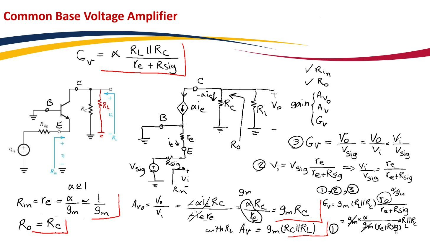 Common-base amplifier: input at emitter, output at collector, base AC-grounded. Non-inverting, gain magnitude similar to CE, low input impedance .
Properties and where it is used
- Input resistance: , very low, only tens of ohms. This makes CB poor for a high-impedance voltage source (it heavily loads the source), but good as a current buffer: it accepts a current at low impedance and passes it on to a high-impedance collector.
- Output resistance: high (looking into the collector, or higher when degenerated by the source resistance through the transistor).
- No Miller effect. Because the base is grounded, the collector–base capacitance is not bridged between a swinging input and a swinging output, so it isn’t multiplied by the gain. This removes the dominant high-frequency pole that limits the CE stage, so the CB amplifier keeps its gain to much higher frequencies. That’s the single biggest reason to use it.
This is why CB sits on top of a CE stage in a Cascode amplifier: the CE stage provides the transconductance, the CB stage buffers its output current up to a high impedance without the Miller penalty, giving high gain and wide bandwidth.
The discrete version uses the same four-resistor Voltage-divider bias as the CE amplifier, but the signal is coupled into the emitter and the base is held at AC ground by a Bypass capacitor. No emitter bypass capacitor, since the emitter is the signal node.
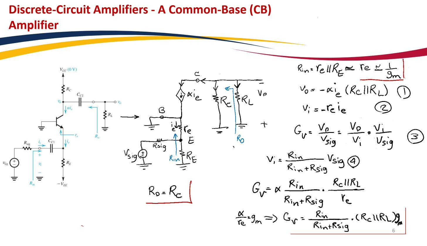 Discrete-circuit common-base amplifier: full layout with coupling and bypass capacitors.