Saturation mode is the BJT region where both junctions are forward-biased. The transistor is “on hard”: fully turned on, collapses to a small value, and the collector current is set by whatever the external circuit can supply, not by . This is the BJT’s closed-switch state in digital logic.
Naming warning. “Saturation” means the opposite thing for a BJT than for a MOSFET. MOSFET saturation is the amplifying region; BJT saturation is the on-hard, fully-conducting region. The MOSFET region matching BJT saturation is the triode region. Keep the BJT operating modes map straight or this will bite you.
What happens physically
Start in active mode and keep driving the base harder. Active mode wants , so more base current demands more collector current. But the collector current has to flow through the external collector circuit (typically to ), and each extra milliamp drops more voltage across , pulling the collector voltage down toward the emitter. Eventually gets so small that the collector–base junction also becomes forward-biased. At that point you have left active mode: both EBJ and CBJ are forward-biased, and that is saturation.
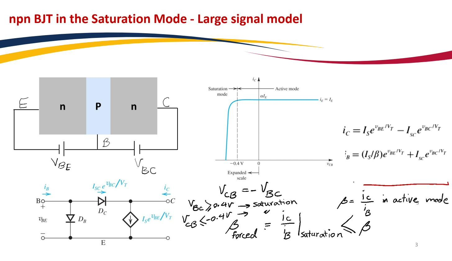
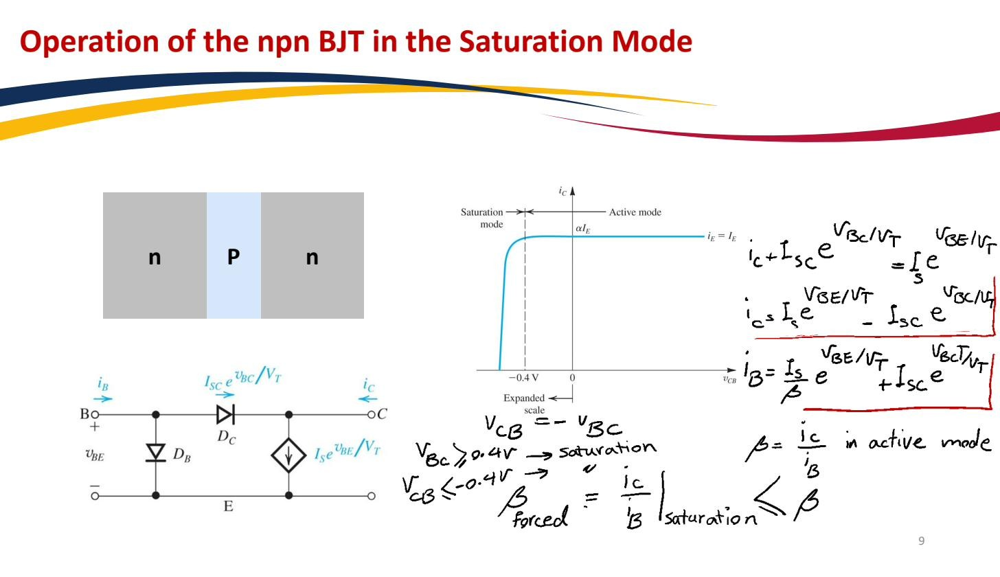 Operation of the npn BJT in saturation: both junctions forward-biased, small (about 0.2 V), and set by the external circuit, not by .
and the model
In saturation is pinned to a small, roughly-constant value called , typically 0.1–0.3 V (a representative number is 0.2 V). The base–emitter still looks like a forward diode, so as in active mode. The simplified large-signal model in saturation is therefore: a fixed 0.7 V from base to emitter, and a fixed from collector to emitter. The full diode-pair picture has both junctions forward; the edge of saturation (the boundary with active mode) is where the CBJ just starts to conduct, around .
 Saturation large-signal model: fixed (same as active) and fixed across collector–emitter; the edge of saturation sits at .
The relation does NOT hold here
Forgetting this is how most students wreck a BJT problem. In saturation the extra base current you push in does not produce proportionally more collector current. The collector current is whatever the external circuit allows, and the surplus base current “spills over” into recombination without showing up at the collector. Define in saturation; it is much smaller than the device’s actual .
So the workflow is always: assume active, solve, then check. If the active-mode solution predicts below about 0.3 V (or worse, negative), the active assumption is false and the device is actually in saturation. You then redo the analysis using as the known quantity and let fall out of the external circuit instead. A full worked saturation-check failure is in BJT DC analysis.
As a switch, saturation is the “closed” state (small voltage drop, current limited by the load) and cut-off is the “open” state.