The MOSFET large-signal model is the equivalent circuit used for DC analysis, i.e. finding a circuit’s operating point. It represents the full, nonlinear behaviour of the transistor at the bias point, before any small-signal linearisation.
The model
For a MOSFET in saturation, the model is a single voltage-controlled current source connected between the drain and the source, delivering
The current is controlled by the gate-source voltage through the MOSFET square-law (, the device MOSFET transconductance parameter, the Threshold voltage). The gate is an open circuit: no DC gate current flows because the gate is insulated by the Gate oxide. If Channel-length modulation matters, add an output resistance in parallel with the current source, between drain and source.
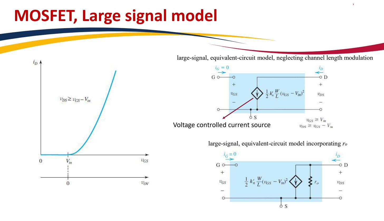 Drain current as a VCCS ; add for channel-length modulation.
Where it sits in the model hierarchy
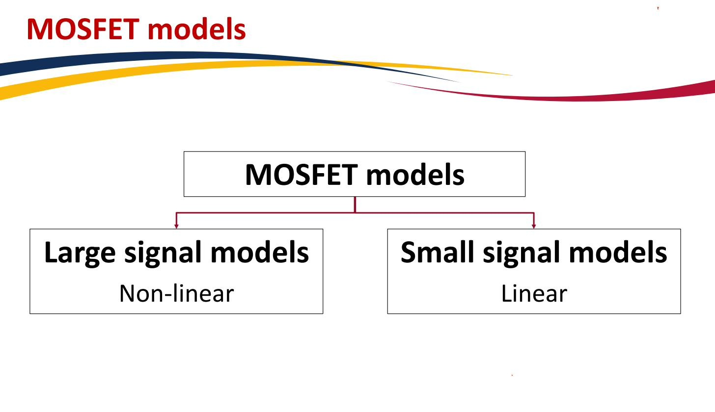
There are two models for the MOSFET and they answer different questions:
- The large-signal model is nonlinear (the controlled source depends on quadratically) and finds the DC operating point, see MOSFET DC analysis. Use it once, to solve for , , .
- The Small-signal model is linear and handles AC analysis of small signals riding on that bias point. You get it by linearising the large-signal law about the operating point you just found: the slope of the square-law becomes (see MOSFET transconductance).
So the workflow is always: large-signal model → solve DC → linearise → small-signal model → solve AC. Each model is exact within its purpose and useless outside it. The large-signal model carries the nonlinearity you need for biasing; the small-signal model throws it away to get a tractable linear AC circuit.
 Large-signal (nonlinear) for DC; small-signal (linear) for AC about a bias point.