A limiter (also called a clipper) is a diode circuit that keeps an output voltage from going above some threshold, below another, or both, leaving signals inside the safe band untouched and flattening anything outside it. The flat regions look like the waveform was “clipped” with scissors, which is where the second name comes from.
How it works
The basic limiter is a diode (optionally with an offset battery or a Zener diode) connected so it stays off while the input is in the allowed range and turns on the moment the input tries to exceed the threshold. When it turns on it clamps the output to the threshold value; the rest of the time it is invisible and the signal passes through unchanged. A series resistor absorbs the difference between input and clamped output when the diode conducts.
These are passive limiters: no amplifying device, so the gain of the linear (pass-through) region is . The transfer characteristic vs is piecewise-linear: a sloped segment of slope (here unity, , for a simple resistive limiter) in the pass region, and a flat segment at the clamp level once the diode conducts. Whether it clips the top, the bottom, or both depends on diode orientation and how many diodes you use.
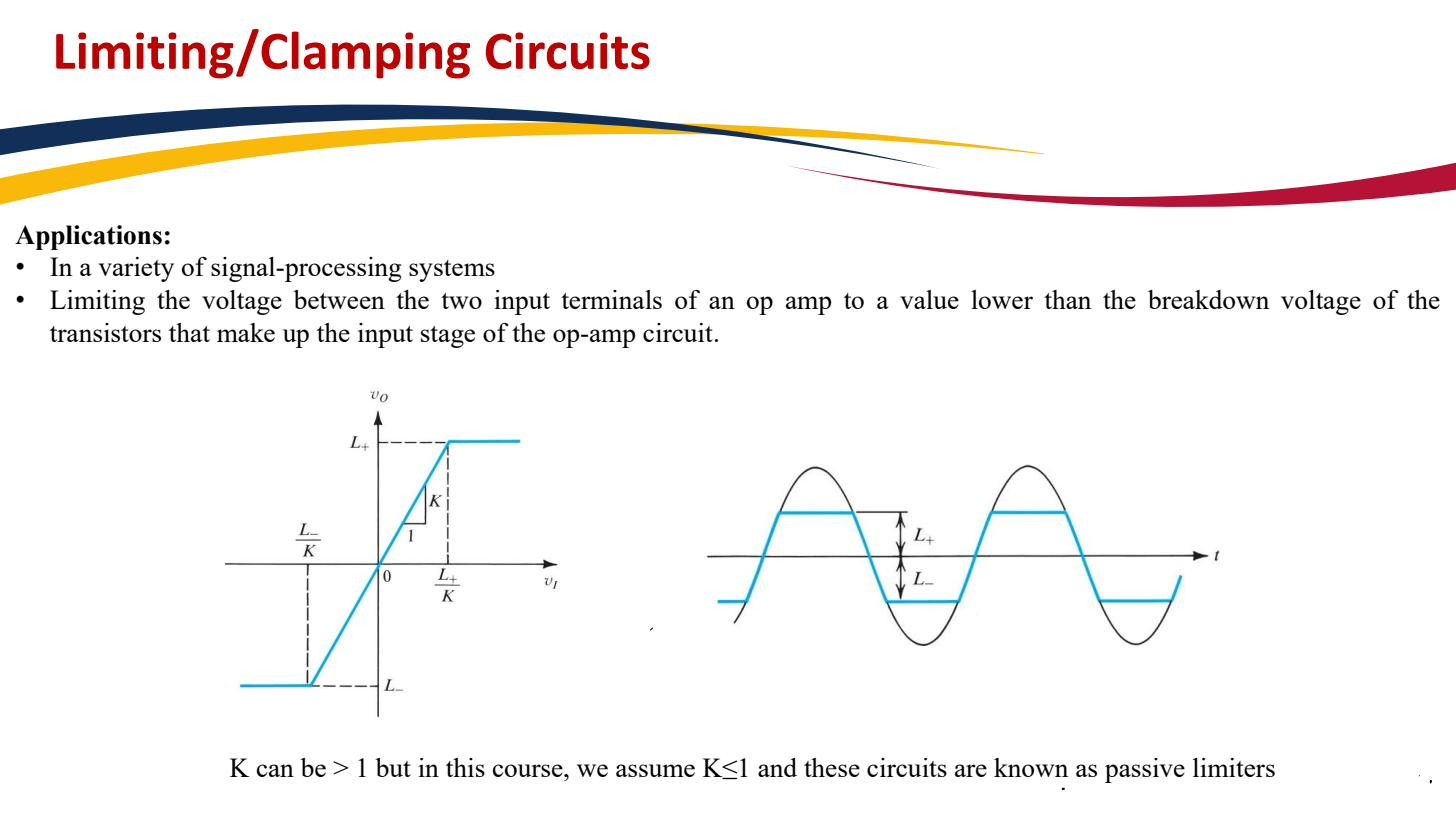 Limiter circuits; passive; output clamped above/below thresholds.
Why it is useful
Limiters protect the inputs of sensitive circuits (op-amp inputs, analog-to-digital converters) from voltages outside their safe operating range. A spike that would damage the downstream circuit gets flattened at a harmless level before it arrives. They are also used deliberately for waveshaping, e.g. squaring off a sine.
The standard catalogue
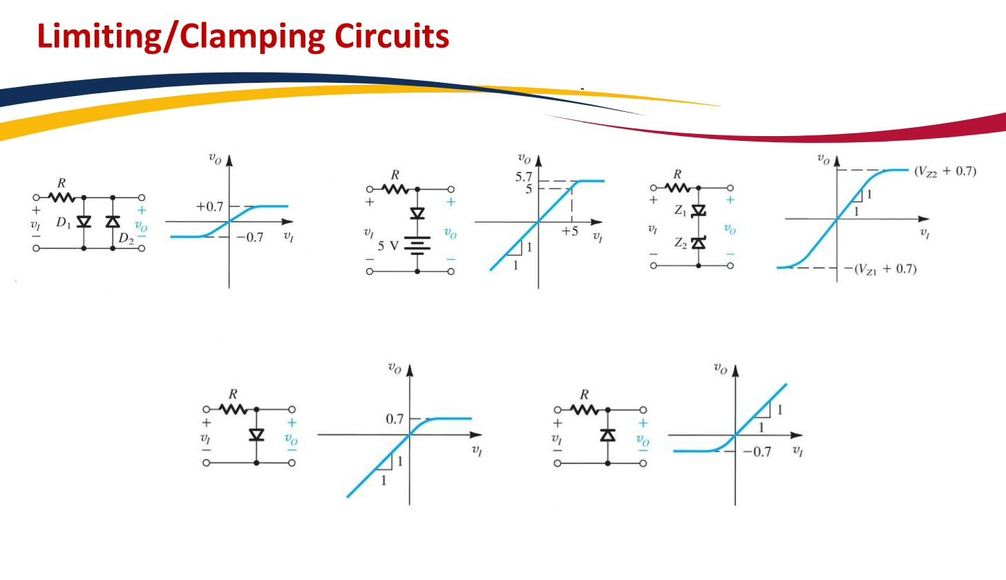 Catalogue of single/two-diode limiters and their transfer characteristics.
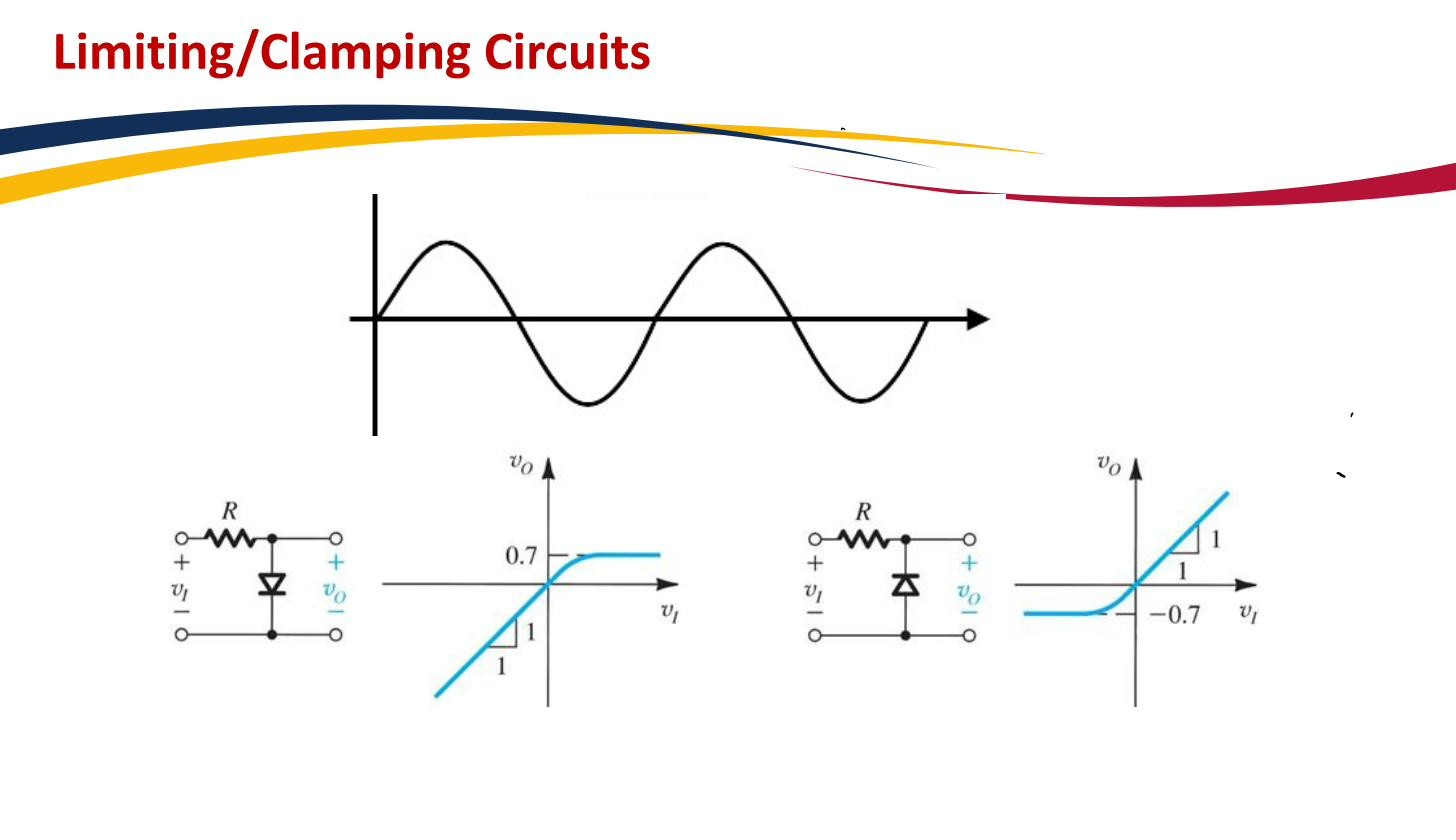
- Single diode — clips at V (the diode’s own drop sets the level).
- Diode + 5 V offset battery — clips at V; the battery raises the threshold to (battery ). Adjustable clip level.
- Two anti-parallel diodes (one each way, in parallel) — clips symmetrically at V; whichever polarity the input takes, one diode conducts.
- Two back-to-back Zeners — clips symmetrically at . On each polarity one Zener is in Reverse breakdown (contributing ) and the other is forward biased (contributing its V), so the level is set cleanly by without any separate bias supply.
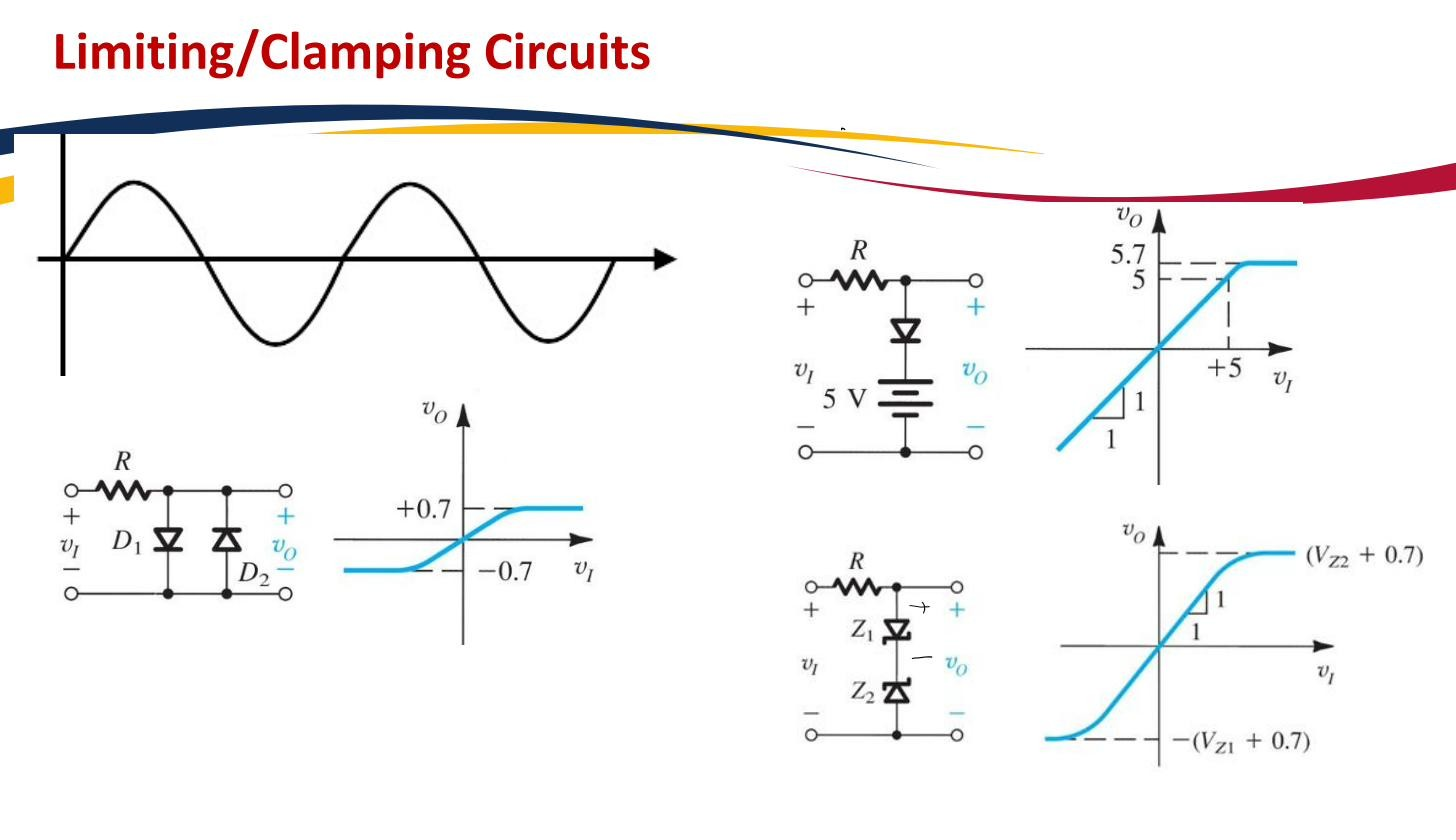 A sine through various limiter configurations, showing how each clips.
The Zener limiter is convenient because the clip level comes from the device’s breakdown voltage rather than from a battery you have to provide and maintain.
 Zener-diode limiter; breakdown sets the clip level without a separate bias supply.
A limiter flattens the extremes of a waveform. A Clamper circuit does something different: it shifts the whole waveform vertically without changing its shape. Combining the two ideas gives the Voltage doubler.