A decoder converts a binary-encoded input into a one-hot output. With input bits, it produces output lines, exactly one of which is asserted at any time: the line whose index matches the input value.
So a 2-to-4 decoder takes 2 inputs and 4 outputs: input asserts , input asserts , etc. Output corresponds to minterm , the AND of the input bits in their appropriate complemented/uncomplemented combination.
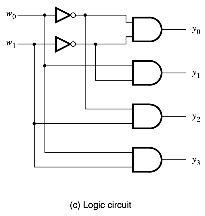
For inputs and outputs, each output is a different -input AND of the input lines (and their complements). The whole decoder is a parallel computation of every minterm.
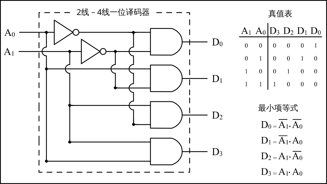 Image: 1-bit 2-to-4 line decoder, CC BY-SA 3.0 — same circuit drawn in standard textbook style: two address bits generate their complements and feed four AND gates, one per output minterm .
Why this is useful
Three common uses:
-
Address decoding. A processor’s address bus selects one memory location out of many. The decoder takes the address bits and produces a single chip-select line that activates the matching memory chip or register.
-
Function generation. Combine the decoder outputs with an OR gate, and you get any SOP expression directly. The decoder produces all minterms; the OR picks which ones contribute to your function.
-
Used as a Demultiplexer. Adding a data input feeds it through to whichever output the address selects.
Enable input
Decoders typically have an enable input, often labelled (with "" a superscript meaning enable — not ” subscript ” or some bit count ). When , the decoder works normally. When , all outputs are forced low; the decoder is disabled. Some texts use , , or for the same signal.
This matters for two reasons:
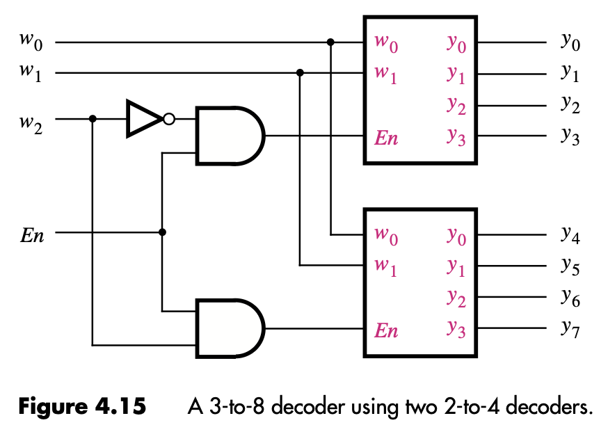
- Building bigger decoders from smaller ones. A 3-to-8 decoder can be built from two 2-to-4 decoders, with the third input bit driving the enables (one decoder enabled when bit 2 is high, the other when bit 2 is low).
- Power and bus management. Disabled decoders don’t drive their outputs, so multiple decoders can share output wires safely: one drives, the others stay quiet.
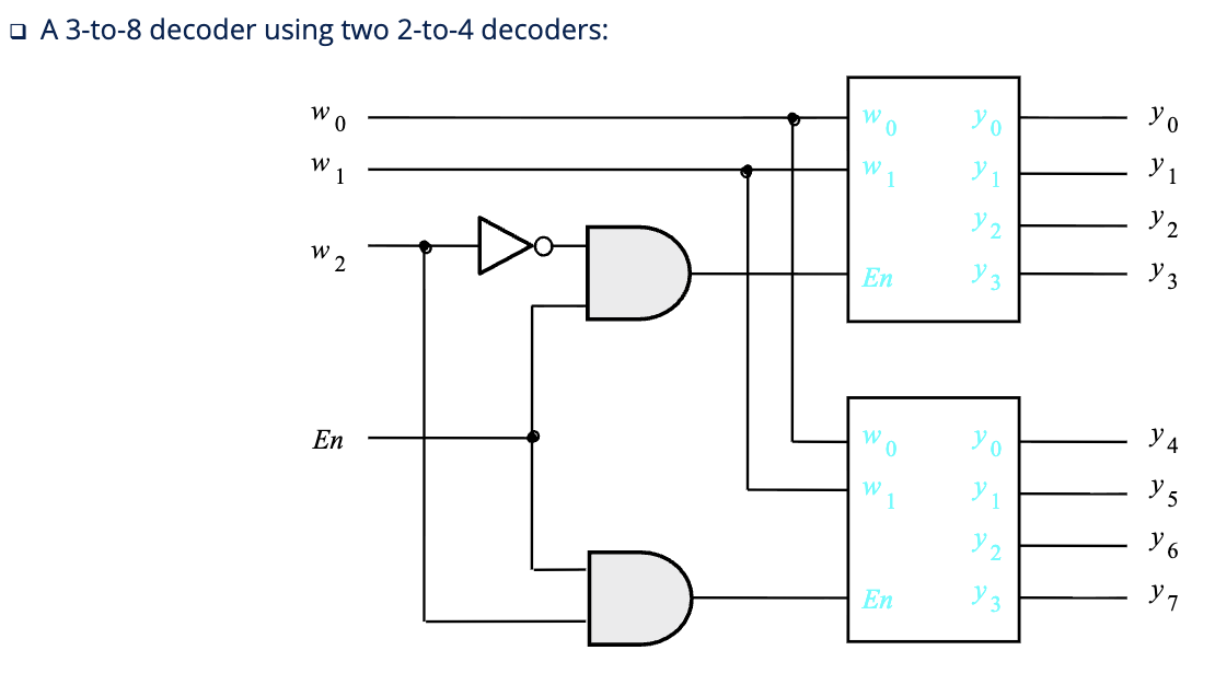
In the diagram above: when , the upper decoder’s enable is on (and the lower one’s is off via the inverter), so behave normally and stay low. When , the roles swap.