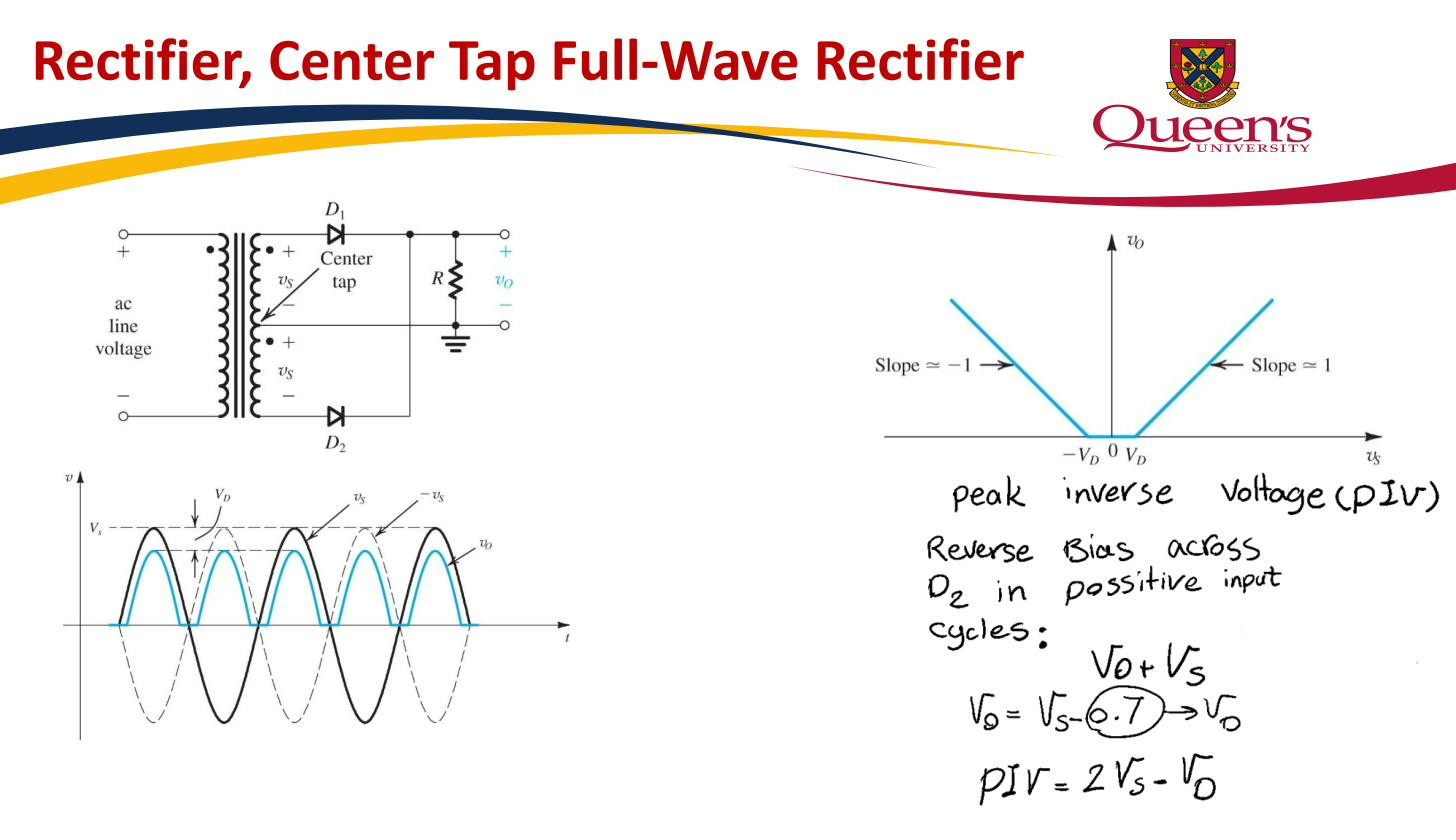
A Full-wave rectifier built from a transformer whose secondary winding has a centre tap, plus two diodes. The centre tap is the common ground for the load; the two ends of the secondary each feed the load through their own diode. Each diode handles one half-cycle, so the load gets a positive hump every half-period.
How it works
Label the two secondary ends “top” and “bottom”, with the centre tap as the reference (0 V). The winding is symmetric, so when the top is at relative to the tap, the bottom is at , and vice versa. The two halves are always equal and opposite. Both diodes point at the load (anodes to the winding ends, cathodes joined at the load).
- Positive half-cycle: top is positive. The top diode is forward biased and conducts, driving current from the top half of the winding, through the diode, into the load, and back via the centre tap. The bottom diode is reverse biased (its anode is at ) and is off.
- Negative half-cycle: the top is negative, so the bottom is positive. Now the bottom diode conducts, driving current through the load in the same direction (still load-positive, returning via the tap). The top diode is off.
Either way the load current flows the same way, so the load voltage is always positive — full-wave rectification. The output frequency is twice the input frequency, and only one diode drop is ever in the load path, so the peak output is .
 Two diodes share the load, one per half-cycle; output frequency twice the input.
The two costs
It needs a centre-tapped transformer, and at any instant only half the secondary is delivering power (the other half is idle, reverse-biasing its diode). That is poor copper utilisation compared with the Bridge rectifier, which keeps the whole winding active.
Each diode’s Peak inverse voltage is . Consider the off diode on the positive half-cycle: its cathode is tied to the load, which is at about (driven there by the conducting diode). Its anode is at the bottom end of the winding, which is at . The reverse voltage across it is therefore . So each diode must be rated for twice the peak voltage, the major disadvantage versus the bridge, whose PIV is only .